Lecture 03 - Transistors
Goals
- learn the behavior of PMOS and NMOS transistors
- learn how to use transistors to build basic Boolean operations
Logic in circuits
So, the question is - how do we implement these three operations in hardware?
Our starting place is the switch – like a light switch opening and closing the switch lets the electricity through
We are going to make two adjustments to your mental model
Now imagine that we have a switch that can be opened and closed based on another electrical signal (we call these relays)
The very first computers made use of electro-mechanical relays One of the first computer “bugs” was an actual moth that had gotten stuck in one of these. It was taped into the log book by Grace Hopper, who thought it funny that the “bug” turned out to be a real one
These were soon replaced by vacuum tubes
Transistors
The real innovation came with the transistor - invented by John Bardeen, Walter Brattain, William Shockley of Bell Labs in the late 40’s
they were far faster, and more reliable and energy efficient than vacuum tubes, and since they were developed using semiconductors, they could be shrunk as we learned more about building integrated circuits
we have two types of semiconductor - PMOS - positive metal-oxide semiconductor - NMOS - negative metal-oxide semiconductor
Both types have three pins - source (you can roughly think of this as the input) - drain (you can think of this as the output) - gate (you can roughly think of this as the control)
NMOS
| gate | source | drain | |
|---|---|---|---|
| 0 | 0 | U | |
| 0 | 1 | U | |
| 1 | 0 | 0 | |
| 1 | 1 | U |
PMOS
| gate | source | drain | |
|---|---|---|---|
| 0 | 0 | U | |
| 0 | 1 | 1 | |
| 1 | 0 | U | |
| 1 | 1 | U |
The behavior of these is a little counter intuitive. It isn’t quite as pure as our switch metaphor. This is why I describe the source and gate as being roughly like the input and the control. The truth is that it is the combination of the two values that produces either a 0 or a 1 (depending on the transistor type)
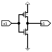
build a NOT
This is the start of our toolbox – now we want to use these to build the next level up the hierarchy
We can break this down into individual pieces
We need a 1 when the input is 0, how do we get that? A PMOS transistor does that if we put a 1 on the source and our input on the gate
We also need a 0 when the input is 1 An NMOS transistor does that when there is a 0 on the source and our input on the gate
We now have two circuits, but we need a single output
We can observe that when the two circuits are not outputting the desired value, they are floating Also, the two are never driving their output at the same time
So, we can just wire the outputs together!
Note that this only works because the outputs float most of the time – we never wire together two outputs that both have a value at the same time!
Now we want to check our circuit with a test plan in this case, we can enumerate all possible values of our input and make sure we get the desired output (i.e. our truth table)
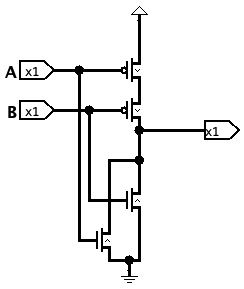
build a NOR
The next tool we will build is something called a NOR gate – NOT OR
| A | B | A+B | |
|---|---|---|---|
| 0 | 0 | 1 | |
| 0 | 1 | 0 | |
| 1 | 0 | 0 | |
| 1 | 1 | 0 |
Again, we can take this piece by piece
Start with the situation where this outputs a 1 We know how to get a 1 when an input is 0, but how do we make sure that both inputs are 0? Answer: wire them in series
We then can deal with each of the other rows separately giving us three separate outputs
Again they are mutually exclusive, or the same value, so we can wire them together (which gives us a pair of NMOS transistors in parallel)
Again, we form our test plan (which is again an exhaustive enumeration) and test all of the various inputs and outputs
Build an OR
we could follow the same steps, OR use the tools we have already built…
Mechanical level
Skills
- evaluate the output of a circuit of transistors