---
title: "Error Correction"
format:
html:
toc: true
number-sections: true
execute:
echo: false
---
::: {.hidden}
$$
\newcommand{\braket}[2]{\langle{#1}|{#2}\rangle}
\newcommand{\ketbra}[2]{|#1\rangle\!\langle#2|}
\newcommand{\proj}[1]{|#1\rangle\!\langle#1|}
$$
:::
[Pre-class notes](HandWrittenNotes/ErrorCorrectionF25Class.pdf)
[In-class notes](HandWrittenNotes/ErrorCorrectionF25Class3Post1.pdf)
## Learning Goals
- Describe errors in quantum/classical systmes
- Describe repetition codes and why they work
- Analyze how a quantum repetition code corrects errors
## Errors?
This semester, we have been learning about how great quantum computers and devices are. But if they are so amazing, why haven't we built one? Because of
**Errors!**
## Errors in Classical Computers
Cosmic rays (protons or other nuclei moving at nearly the speed of light) are believed to be the source of most errors in classical computers. They are believed to cause approximately $1$ bit flip per 4 GB of data per day. This is so infrequent that the effect of errors is generally ignored, but there have been some famous glitches (called "soft errors") that are [suspected to be caused by cosmic ray errors](https://www.bbc.com/future/article/20221011-how-space-weather-causes-computer-errors):
- A case of a pace maker malfunctioning (started on a plane, where incidence of cosmic rays are more likely)
- A vote counting machine clitch
- A plane that dropped in midair
- A Super Mario 64 teleporting incident
So even though we usually don't worry about these issues, for very sensitive cases, or especially computers in space, we need a way to correct errors.
### Repetition Code
Here is a circuit diagram for a repetition code:
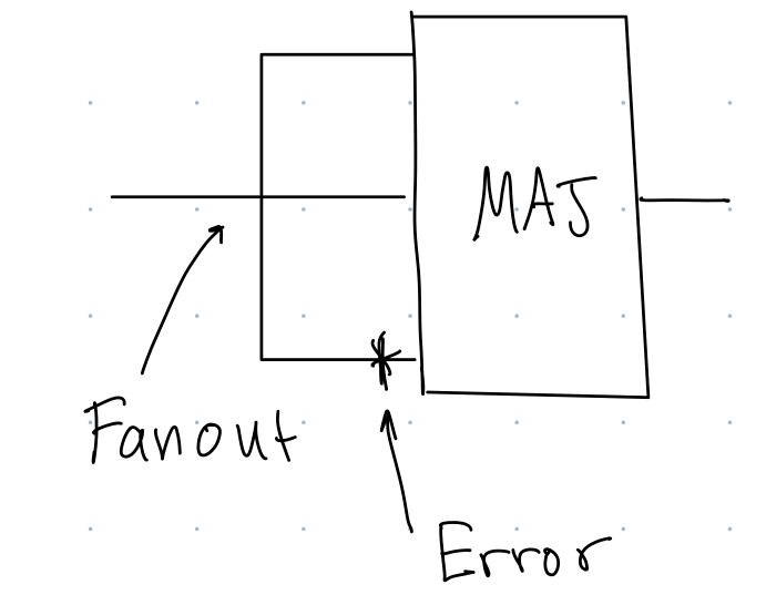{#fig-rep width=50%}
We read the diagram in @fig-rep from left to right. The lines represent classical bits. We see that the input bit goes into a fanout gate, which copies the value of the original bit into 3 copies, so if the circuit started with a 0, you would get 000 after the fanout, and if the circuit started with a 1, you would get $111$ after the fanout. Then suppose an bit-flip error occurs on any of the bits. In @fig-rep, if we started with a $0$, and the error happened on the bottom bit, the right before the majority gate (MAJ), we would have the state 001. Then the majority gate takes the majority value of the three input bits. In this case, the majority of 001 is 0, so the majority gate would output a 0. Then you can repeat this process continually to correct any errors. As long as the rate of errors is so low that you are very unlikely to get two errors in one time step, as is the case with cosmic ray errors, this code will keep errors from affecting the output of the computation.
Note that this error correcting code works whether a 0 or 1 is the input bit. Thus this works without having to know the input bit ahead of time.
## Errors in Quantum Computers
There are more sources of errors in quantum errors that I can list, but here are a few:
- control lasers/pulses not perfect (can be imperfect in shape, frequency, focus, intensity)
- imperfect vacuum (so random atoms bump into your qubits)
- imperfect magnetic/electric field shielding
- heat (many types of quantum computers need to be very cold to work)
::: {.callout-tip appearance="simple"}
### ABCD Question
Why can't we just use the repetition code to correct errors in our qubits?
A) MAJ is not reversible
A) Repetition doesn't correct phase errors (like unwanted $Z$ gates)
A) We can not implement fanout because we can not copy qubits
A) There are uncountably infinitely many errors that we might have to deal with, rather than 3 possible errors in the case of the repetition code.
:::
## Shor's Repetition Code
Peter Shor (the same Shor of Shor's factoring algorithm), came up with the first quantum error correcting code.
### Encoding
The encoding for part of the code is as follows
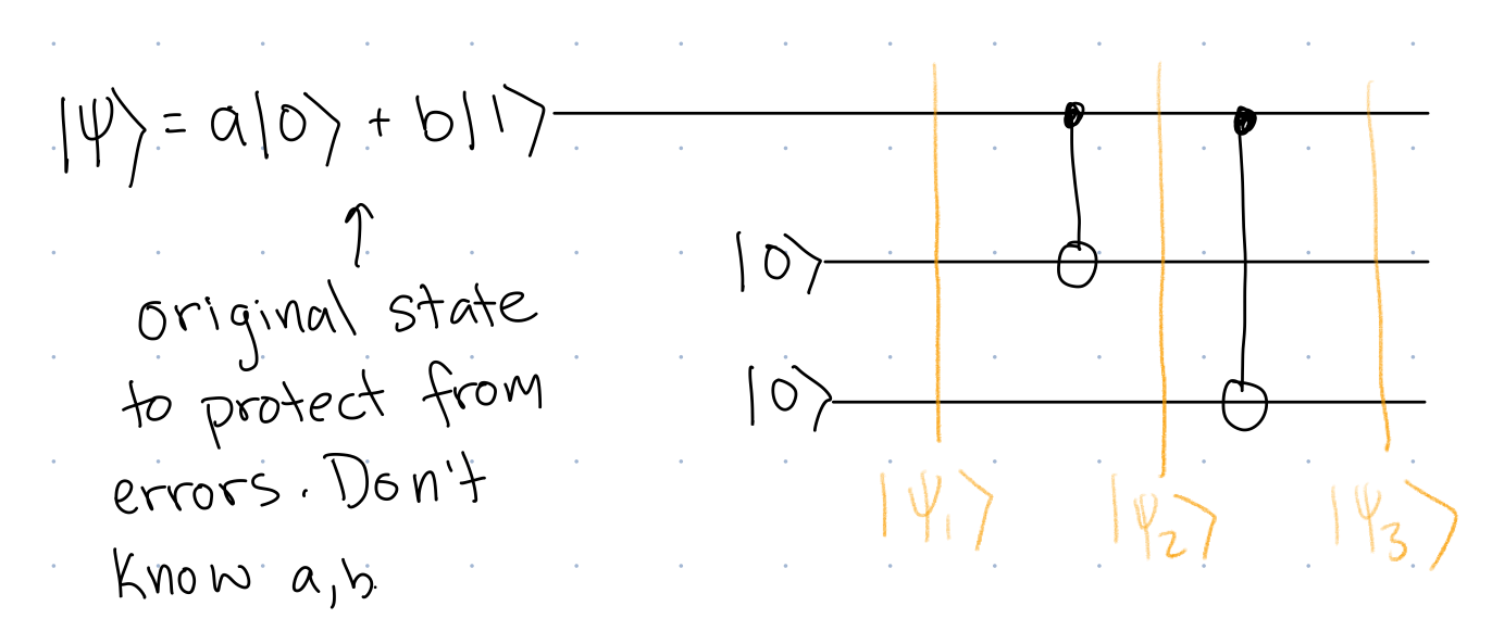{#fig-enc width=70%}
The circuit in @fig-enc shows how a single qubit state is encoded into 3 qubits. Just like in the classical case, we assume we don't know ahead of time the value of the input bit, in this case, we assume we don't know the values of $a$, $b$, the input amplitudes.
Let's analyze this circuit:
$$
\begin{align}
\ket{\psi_1}&=(a\ket{0}+b\ket{1}))\ket{0}\ket{0} &\\
&=a\ket{000}+b\ket{100} & \textrm{ Distribute tensor product and combine ket-ket-ket}\\
\ket{\psi_2}&=CNOT_{12}(a\ket{000}+b\ket{100})&\\
&=aCNOT_{12}\ket{000}+bCNOT_{12}\ket{100}&\textrm{Distribute CNOT, commute amplitudes}\\
&=a\ket{000}+b\ket{110}&\textrm{Apply CNOT}\\
\ket{\psi_3}&=CNOT_{13}(a\ket{000}+b\ket{110})&\\
&=a\ket{000}+b\ket{111}
\end{align}
$$
We call $a\ket{000}+b\ket{111}$ a "logical qubit." It only encodes 2 amplitudes, like our original single qubit $a\ket{0}+b\ket{1},$ but it now uses three qubits to do so, in order to build in redundancy.
We call $\ket{000}$ the "logical" $0$-state, denoted $\ket{0_L}$ and we call
$\ket{111}$ the "logical" $1$-state, denoted $\ket{1_L}$. So we can write
$$
a\ket{000}+b\ket{111}=a\ket{0_L}+b\ket{1_L}
$$
### Correcting An Error
The correcting part of the circuit consists of a syndrome measurement, which detects the error that occurred on the logical qubit, along with a part of the circuit that corrects the error to return the state to the original logical state.
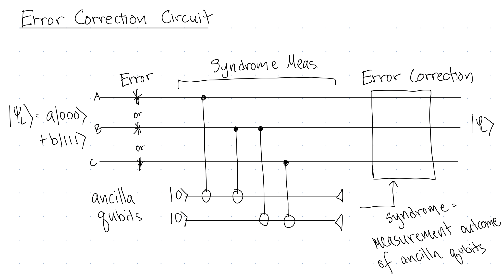{#fig-correct width=80%}
I know what you are thinking, "Oh yay! Another partial measurement!"
However, we are going to learn a different approach to analyzing this partial measurement, called a *Projective Measurement*. Instead of analyzing the series of control-nots and partial measurement that is the syndrome measurement, we will encapsulate all of those gates and partial measurement into a single projective measurement.
### Projective Measurement
A projective measurement is described by a set of projectors:
$$
M=\{P_0,P_1,P_2\dots, \}.
$$
where $P_i$ each denote a possible outcome of the measurement.
Each projector looks like:
$$
\begin{align}
P_0&=\proj{\phi_1}+\proj{\phi_4}\\
P_1&=\proj{\phi_3}\\
P_2&=\proj{\phi_2}+\proj{\phi_5}+\proj{\phi_6}\\
\vdots
\end{align}
$$
where $\ket{\phi_i}$ should be an $N$-dimensional state, where $N$ is the dimension of the system after partial measurement. (There is also a technical condition that $\sum_iP_i=I$, but you will not need to use this fact in this class.)
If we make a projective measurement $M$ on a state $\ket{\psi}$,
* The probability of outcome $P_i$ is $\bra{\psi}P_i\ket{\psi}$.
* If get outcome $i$, the state collapses to
$$
\frac{P_i\ket{\psi}}{\sqrt{Pr(i)=\bra{\psi}P_i\ket{\psi}}}.
$$
We want to define a projective measurement that is equivalent to the syndrome measurement (in red box in @fig-synd-replace)
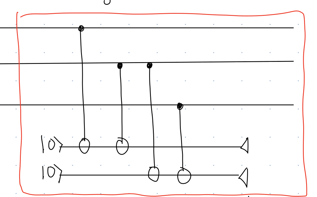{#fig-synd-replace width=80%}
Note that after measurement, there are 3 qubits, so the states involved in our projections should be 3-qubit states. We are measuring the two additional qubits in the standard basis, so there are 4 possible outcomes to the partial measurement. This means that we should have 4 possible outcomes to our projective measurement. The projective measurement that corresponds to
@fig-synd-replace is
$$
M=\{P_0,P_1,P_2,P_3\}
$${#eq-M1}
where
$$
\begin{align}
P_0=&\proj{000}+\proj{111}\\
P_1=&\proj{001}+\proj{110}\\
P_2=&\proj{010}+\proj{101}\\
P_3=&\proj{100}+\proj{011}
\end{align}
$$
::: {.callout-tip appearance="simple"}
### ABCD Question
[QC4 warm-up]
If we measure $\ket{\psi}=\sqrt{\frac{1}{6}}\ket{000}+\sqrt{\frac{2}{6}}\ket{001}+\sqrt{\frac{3}{6}}\ket{110}$ with $M$ from @eq-M1, which outcomes are possible
A) $P_0$
A) $P_1$
A) $P_2$
A) $P_3$
:::
::: {.callout-tip appearance="simple"}
### Group Exercise
[QC4 warm-up]
If we measure $\ket{\psi}=\sqrt{\frac{1}{6}}\ket{000}+\sqrt{\frac{2}{6}}\ket{001}+\sqrt{\frac{3}{6}}\ket{110}$ with $M$ from @eq-M1, and get outcome $P_1$, what is the resultant state?
:::
::: {.callout-important}
Note that after a projective measurement, the state is in a superposition of the states that appear in that particular measurement outcome.
:::
::: {.callout-tip appearance="simple"}
### Group Exercise
[QC4]
{#fig-correct2 width=80%}
Consider an "$X$ Rotation" error of the form
$$ R_X(\Theta) = \cos(\theta) I +i\sin(\theta)X$$
on of of the physical qubits of the logical qubit. Such an error is a partial $X$ gate.
This notation means:
$$
R_X(\Theta)\ket{\psi}=\cos(\theta)\ket{\psi}+i\sin(\theta)X\ket{\psi}
$$
Each group should consider an $R_X$ gate on a different qubit of the encoded state.
1. What are the possible outcomes and what does the state collapse to in each case?
2. What error correction procedure should be done in each case?
:::
Shor's repetition code can correct any single qubit X-type rotation error.
### Big Ideas of Quantum Error Correction
* Partial collapse due to the measurement of the ancillas turns a continuous family of errors like $R_X(\theta)$ into a discrete error: either $X$ or $I$.
* Partial collapse provides information on how to correct the error, without destroying the superposition of a state with amplitude $a$ and a state with amplitude $b$.
## Shor's 9-qubit code
The 3-qubit repetition code we saw in the previous section can correct any single qubit X-type rotation. But what if we want to correct any possible single qubit unitary? We need a bigger code!
**The 9-qubit Shor Code**
The 9-qubit code encodes a single logical qubit into 9 physical qubits:
$$
\begin{align}
\ket{0_L}=(\ket{000}+\ket{111})(\ket{000}+\ket{111})(\ket{000}+\ket{111})\\
\ket{1_L}=(\ket{000}-\ket{111})(\ket{000}-\ket{111})(\ket{000}-\ket{111})
\end{align}
$$
For example, if we have a $Z_6$ error (a Z-type error on the 6th qubit), after the projective measurement, if we don't collapse back to the codespace (a superposition of the states: $\ket{0_L},\ket{1_L}$), then we will collapse to
$$
\begin{align}
(\ket{000}+\ket{111})(\ket{000}-\ket{111})(\ket{000}+\ket{111})\\
(\ket{000}-\ket{111})(\ket{000}+\ket{111})(\ket{000}-\ket{111})
\end{align}
$$
Looking at these states, to correct, we want to do the smallest number of operations possible to return to the code space. We can do this by applying a $Z$ operation to any of the middle 3 qubits, and we will return to original superposition states $\ket{0_L},\ket{1_L}$.
However, if we have a $Z_1$ and a $Z_4$ error, we could collapse to the states
$$
\begin{align}
(\ket{000}-\ket{111})(\ket{000}-\ket{111})(\ket{000}+\ket{111})\\
(\ket{000}+\ket{111})(\ket{000}+\ket{111})(\ket{000}-\ket{111})
\end{align}
$$
Now to return to the codespace, the simplest thing to do would be to apply a $Z_7$. But this would actually swap the $\ket{0_L}$ and $\ket{1_L}$ states, resulting in an error. So we can not correct two Z-type errors with this code.
::: {.callout-tip appearance="simple"}
### Group Exercise
[QC4 Challenge]
Which errors can be corrected by Shor's code:
A) $Z_1Z_2$
B) $Z_4Z_8$
C) $Z_1Z_2Z_3$
D) $X_1z_2$
E) $X_1X_2$
F) $X$
:::
## Towards Fault Tolerance
Shor's 9 qubit code can encode a single logical qubit, and can correct any single qubit error with 9 physical qubits. But what if there is a chance of two errors happening at the same time!!
We use *concatenation* and encode each of the physical qubits of the code in another layer of encoding. Thus with two layers of Shor's code, we can correct any two qubit error with 81 physical qubits, encoding 1 logical qubit.
But with more qubits, we have a larger chance of error. We can only keep ahead of accumulating errors if the error rate is small enough.
Currently, some of the best codes can tolerate 99.9% accuracy , and use 1000-10000 physical qubits to encode a single logical qubit.
Currently, some of the best qubits have 99.9% accuracy for two qubit gates, and 99.99% accuracy for 1 qubit gates.