Lecture 10 - State machines
Goals
- Learn how to build sequential circuits
Last time we looked at how we could take our basic memory units and make addressable memory
Today we will look at how we can incorporate memory with other circuits to get interesting behavior
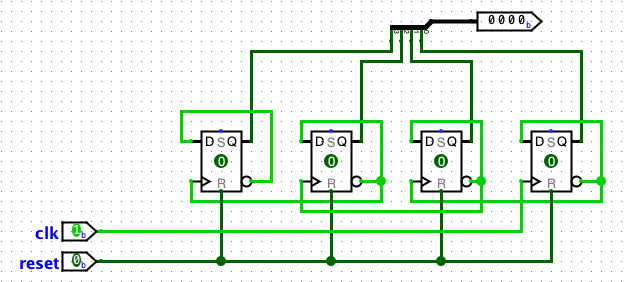
The counter
We can exploit the repetitive nature of counting in binary to build a simple binary counter
Traffic Light
Imagine we have a four way intersection and we want to design a traffic light controller.
We are going to ignore being responsive to traffic -- we are just going to cycle through the light states
We can simplify this to just two lights as well and assume that both the north and south traffic get the same lights and the east and west traffic get the same lights
The cycle will look something like this:
| step | NS lights | EW lights |
|---|---|---|
| 0 | red | red |
| 1 | green | red |
| 2 | yellow | red |
| 3 | red | red |
| 4 | red | green |
| 5 | red | yellow |
We could go through the same process we went through before, but we can also realize that there is no choice here, so our state registers can just be a counter
Then it is just a matter of figuring out when each light is on
| S2 | S1 | S0 | NS red | NS yellow | NS green | EW red | EW yellow | EW green |
|---|---|---|---|---|---|---|---|---|
| 0 | 0 | 0 | 1 | 0 | 0 | 1 | 0 | 0 |
| 0 | 0 | 1 | 0 | 0 | 1 | 1 | 0 | 0 |
| 0 | 1 | 0 | 0 | 1 | 0 | 1 | 0 | 0 |
| 0 | 1 | 1 | 1 | 0 | 0 | 1 | 0 | 0 |
| 1 | 0 | 0 | 1 | 0 | 0 | 0 | 0 | 1 |
| 1 | 0 | 1 | 1 | 0 | 0 | 0 | 1 | 0 |
NS red = S2 + S1 XNOR S0

NS yellow = S2'S1S0'

NS green = S2'S1'S0

EW red = S2'

EW yellow = S2S1'S0

EW green = S2S1'S0'
Soda machine
imagine a simple soda machine it sells 15 cent sodas and only accepts nickels and dimes we will represent the nickels and dimes using a single variable D/N’, which inserts a dime when high and a nickel when low the machine will have one output, which goes high when it has enough change to dispense a soda we want to think about the various combinations of change that you could insert into the machine to get your drink we can draw a state diagram to help us reason about it
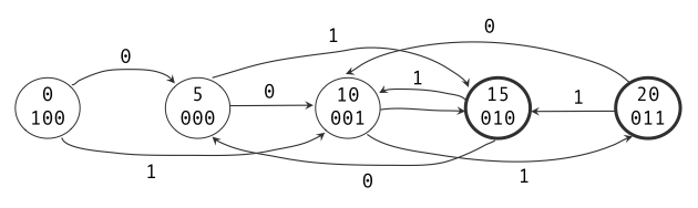
We have a state for each quantity of money in the machine
The dark outline shows the states where we are asserting the soda output indicating that we are dispensing a soda
In the 0.05 credit in the machine
Since each arc represents adding a coin to the machine, we never actually return to the start state
You have probably seen state diagrams like this before (at the very least, if you stick with CS you soon will)
What is different in this class is that we are going to design a circuit that implements it We start by assigning a unique bit pattern to each state Unfortunately, we need three bits since we have five states
There are no rules about how we assign bit patterns to our states, so I made the state we never go into after the start be the one that sets the high order bit to 1
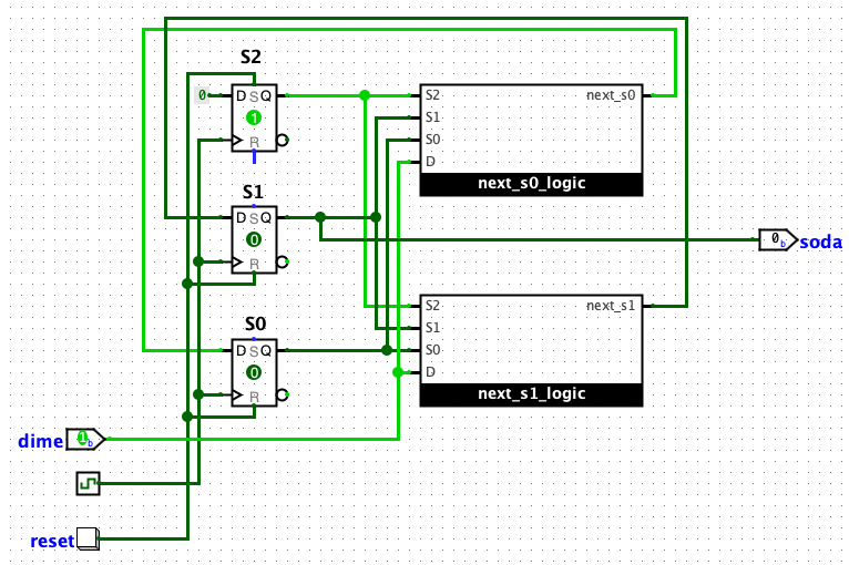
To implement this, we need a flipflop for each bit of the state. We will call these S2, S1, and S0
The input, which we will call D (when D is 1, someone put in a dime, when it is 0, someone added a nickel)
The output we will call soda, and it goes high when the machine dispenses the soda
We need four separate circuits
- each bit of the state needs next state logic, which determines what the next value should be based on the input and the current state. We will refer to the output of these as NS2, NS1, and NS0
- we need a circuit for the output soda which is based solely on the current state
| S2 | S1 | S0 | D | NS2 | NS1 | NS0 | soda |
|---|---|---|---|---|---|---|---|
| 0 | 0 | 0 | 0 | 0 | 0 | 1 | 0 |
| 0 | 0 | 0 | 1 | 0 | 1 | 0 | 0 |
| 0 | 0 | 1 | 0 | 0 | 1 | 0 | 0 |
| 0 | 0 | 1 | 1 | 0 | 1 | 1 | 0 |
| 0 | 1 | 0 | 0 | 0 | 0 | 0 | 1 |
| 0 | 1 | 0 | 1 | 0 | 0 | 1 | 1 |
| 0 | 1 | 1 | 0 | 0 | 0 | 1 | 1 |
| 0 | 1 | 1 | 1 | 0 | 1 | 0 | 1 |
| 1 | 0 | 0 | 0 | 0 | 0 | 0 | 0 |
| 1 | 0 | 0 | 1 | 0 | 0 | 1 | 0 |
Notice that the truth table isn't complete there are a collection of invalid states that we can't get to, so we don't care what our circuit would output if they ever happened (we can actually use this to make our circuits smaller)
soda
we know that we only output the soda in states 010 or 011, so
soda = S2'S1S0' + S2'S1S0
We can simplify this with two observations
First, there is no 110 or 111 so we can just say that if there were, we would assert soda. This may seem like a silly statement, but it means that we can remove the S2 as a variable since it doesn't matter what it is set as
soda = S1S0' + S1S0
notice that S0 appears in both terms -- it doesn't matter what value it is
soda = S1
NS2
We never transition to a state that sets S2 to anything other than 0 (despite starting with it as 1)
NS2 = 0
NS1
Now we just need to read off the SOP from the truth table
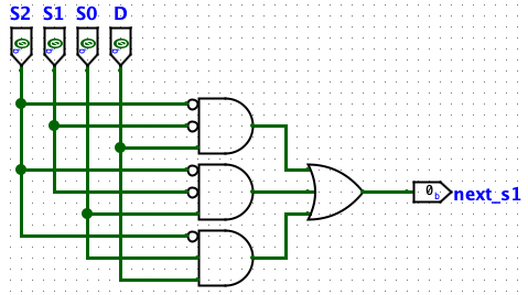
NS1 = S2'S1'S0'D + S2'S1'S0D' + S2'S1'S0D + S2'S1S0D
This simplifies down to (don't worry too much about the process)
NS1 = S2'S1'D + S2'S1'S0 + S2'S0D
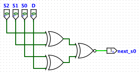
NS0
Again, we go for the SOP
NS0 = S2'S1'S0'D' + S2'S1'S0D + S2'S1S0'D + S2'S1S0D' + S2S1'S0'D
This one has a stranger minification that you really don't need to worry about (just use the SOP in your work)
NS0 = ((S2 XOR S1) XNOR (S0 XOR D))
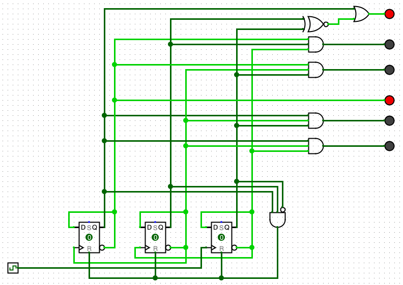
The circuits
NS0
NS1
main circuit
Mechanical level
vocabulary
Skills
Last updated 04/05/2023