Lecture 08 - Memory units
Goals
- Learn the basics about how memory can be made from gates
- Learn how an SR latch works and its limitations
- Learn how a D latch works
- Learn how a D flipflop works and how it difference from a latch
All of the circuits for this lecture are included as sub circuits in the above Logisim file. To download, right click and choose "Save link as..." or the equivalent
SR Latch
cross coupled NOR gates (or NAND gates for inverted logic)
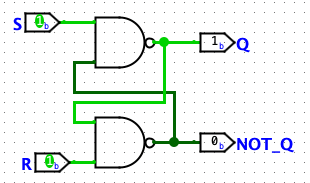
| S | R | Q | Q' | meaning |
|---|---|---|---|---|
| 0 | 0 | 1 | 1 | illegal |
| 0 | 1 | 1 | 0 | set |
| 1 | 0 | 0 | 1 | reset |
| 1 | 1 | last Q | last Q' | hold |
Not that this is no longer combinational logic -- the output isn't solely dependant on the current combination on inputs
sequential logic - output is a function of the input, and all previous inputs (i.e., it has memory)
There are two ways to think about why this works
- it takes time for signal to propagate through real circuits
- at a conceptual level, if there is a 0 on the input of a NAND, the other input doesn't matter -- the output is always 1
This has some odd features
- we have a bonus inverted output
- we have two input that are required to control which value is held
- we have an illegal state that breaks our mental model of what this circuit does
Gated D latch
Two changes
- we replace S and R with a single input that we invert internally
- we add an enable line
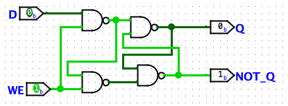
When the enable is low, this holds the inputs to the inner latch to the HOLD state
When the enable is active, then the latch is "transparent" and any changes to D show up on Q
level-triggered - the behavior of the circuit is controlled by the level of the enable line
D Flip-flop
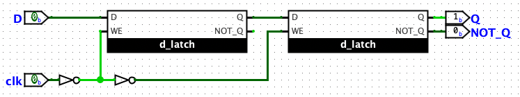
For the flipflop, we add a second latch
- when the enable is low, then any change to D will be visible on the output of the first latch, but since the enable is reversed for the second, ti isn't stored in the second one
- when the enable goes high, we hold on the first latch,. locking in the value, at the same time the second latch is enabled, storing the waiting value
The results is that the stored value is the one that was on the input when the enable line changes from low to high
edge-triggered - the behavior of the circuit is controlled by the change of value of the enable line
Circuits can be controlled on the rising edge like this one or the falling edge (which is what we would get if we removed the first NOT on the control line)
This circuit is so useful that Logisim has one in the Memory library
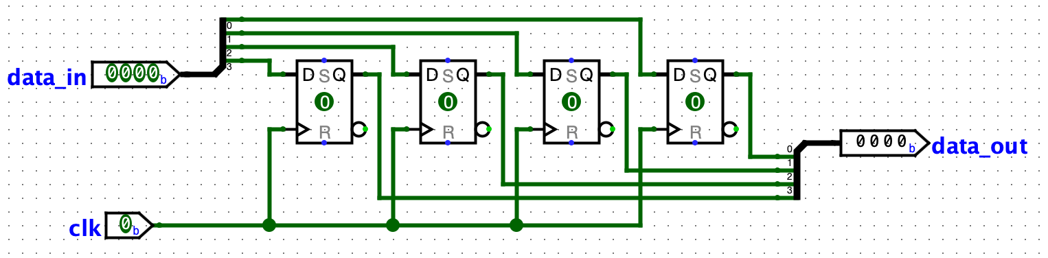
Registers
With the D flip flop we now have the ability to save a single bit of memory.
To save something useful, like a number, we need more than a single bit. We can chain a collection of D flip flops together to get a register.
Here is a four bit register:
Mechanical level
vocabulary
- sequential logic
- edge-triggered
- level-triggered
Skills
Last updated 04/05/2023