We have a simple soda machine that sells fifteen cent sodas. It only takes nickels and dimes. We will represent the amount fed into the machine as a single bit input IN, which is 0 when a nickel is put into the machine and 1 when a dime is put in.
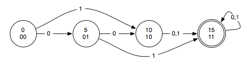
We can represent the behavior of this machine using a state diagram:
Each bubble represents a single state. The top number represents how much money has been entered into the machine. The bottom number is the unique bit pattern we are using to represent this state. We will refer to the two bits of the state as S1 and S0. The double circle indicates the state in which the soda is dispensed.
To implement this, we start by writing it out in a truth table:
| IN | S1 | S0 | S1_next | S0_next | OUT |
|---|---|---|---|---|---|
| 0 | 0 | 0 | 0 | 1 | 0 |
| 0 | 0 | 1 | 1 | 0 | 0 |
| 0 | 1 | 0 | 1 | 1 | 0 |
| 0 | 1 | 1 | 1 | 1 | 1 |
| 1 | 0 | 0 | 1 | 0 | 0 |
| 1 | 0 | 1 | 1 | 1 | 0 |
| 1 | 1 | 0 | 1 | 1 | 0 |
| 1 | 1 | 1 | 1 | 1 | 1 |
Note that I simplified the logic even further by switching the output to be purely a function of the state. So, we only output the soda when we are in state 11.
Now we can write some logic equations.
OUT = S1•S0 S1_next = (IN’•S1’•S0’)’ = IN + S1 + S0 S0_next = (IN’•S1’•S0 + IN•S1’•S0’)’ = S1 + S0’•IN’ + S0•IN = S1 + (S0 ⊕ IN)’
If you aren’t familiar with the notation, the apostrophe is used as equivalent to putting a bar over the expression to negate it when we type (since it is hard to type that bar…)
Don’t worry about the logic reduction. We could have used the original expressions if we wanted. I also did S0_next differently than I did in class. Using the inverted logic makes it a little easier to reduce.